The Ohme Home Pro and Ohme ePod come with a CT clamp included in the box. The CT clamp monitors the total load going through a home and should be installed so that Ohme’s load balancing feature can be enabled. If the load exceeds the maximum that a house can handle, this feature will temporarily reduce the power of the EV charger to prevent a loss of power.
Follow the steps below to see how to install a CT clamp for each Ohme charger.
Jump to:
Ohme Home Pro
Ohme ePod
Take CT clamp reading
Ohme Home Pro
Step 1
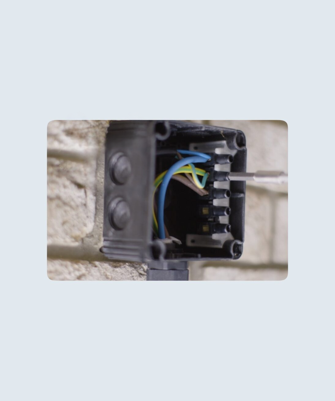
Once the Ohme Home Pro has been fixed to the wall, connect the data cable wires in the junction box.
Note: It is important not to feed the cable through the top of the junction box to minimise the risk of water ingress.
Step 2
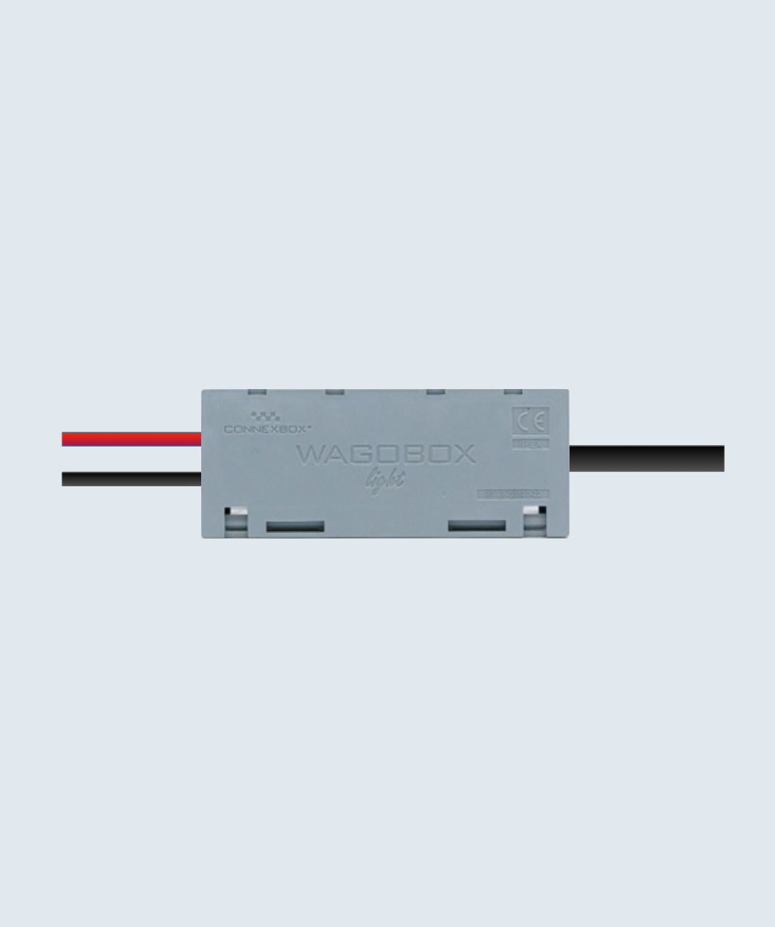
Connect the other end of the data cable to the Wago light box (included with the Ohme Home Pro) and join with the wires from the CT clamp.
Step 3
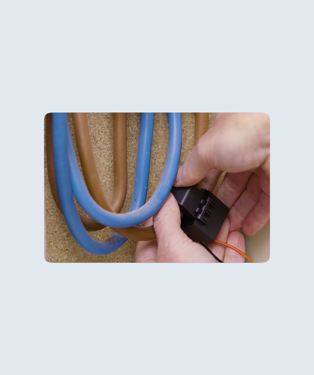
Attach the CT clamp closest to the cable exiting the smart meter.
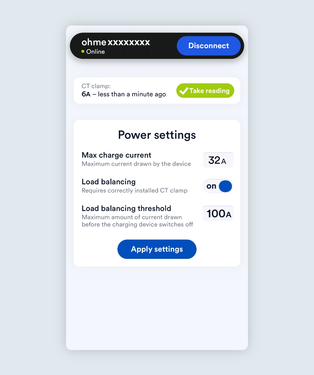
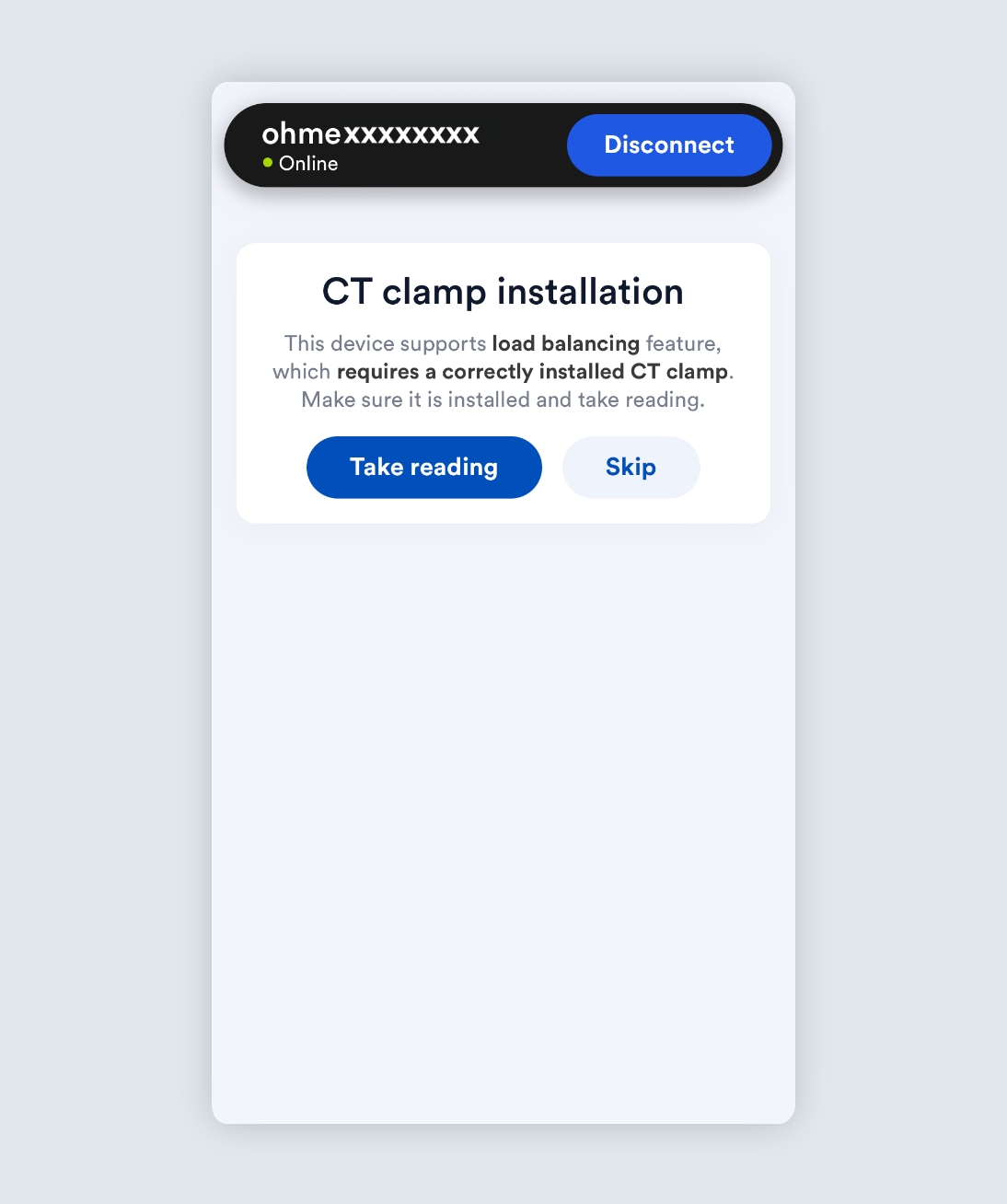
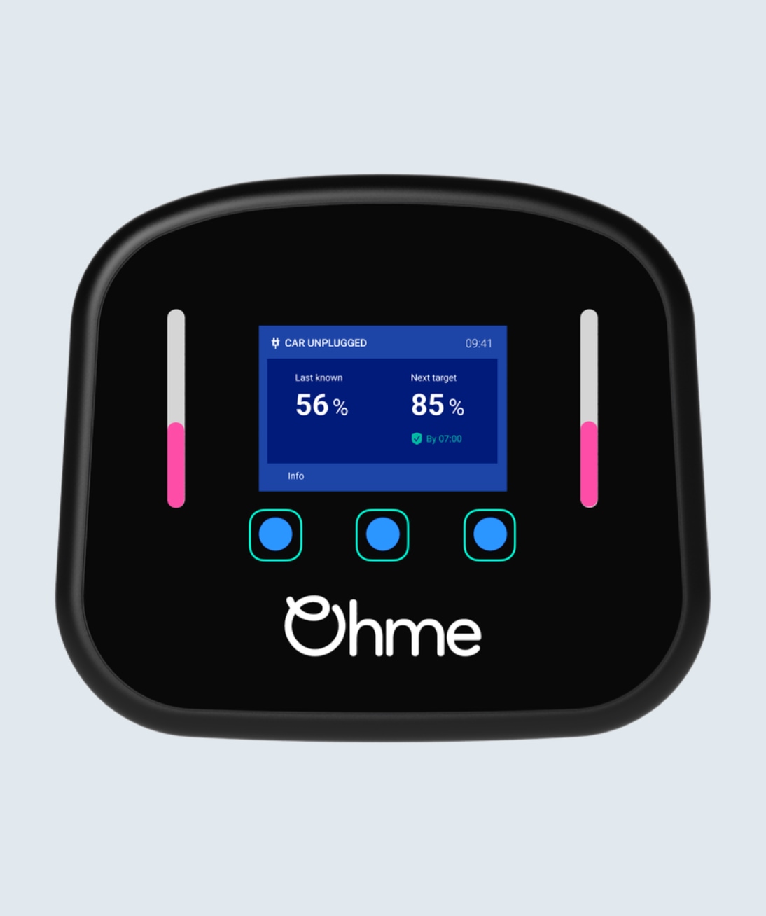
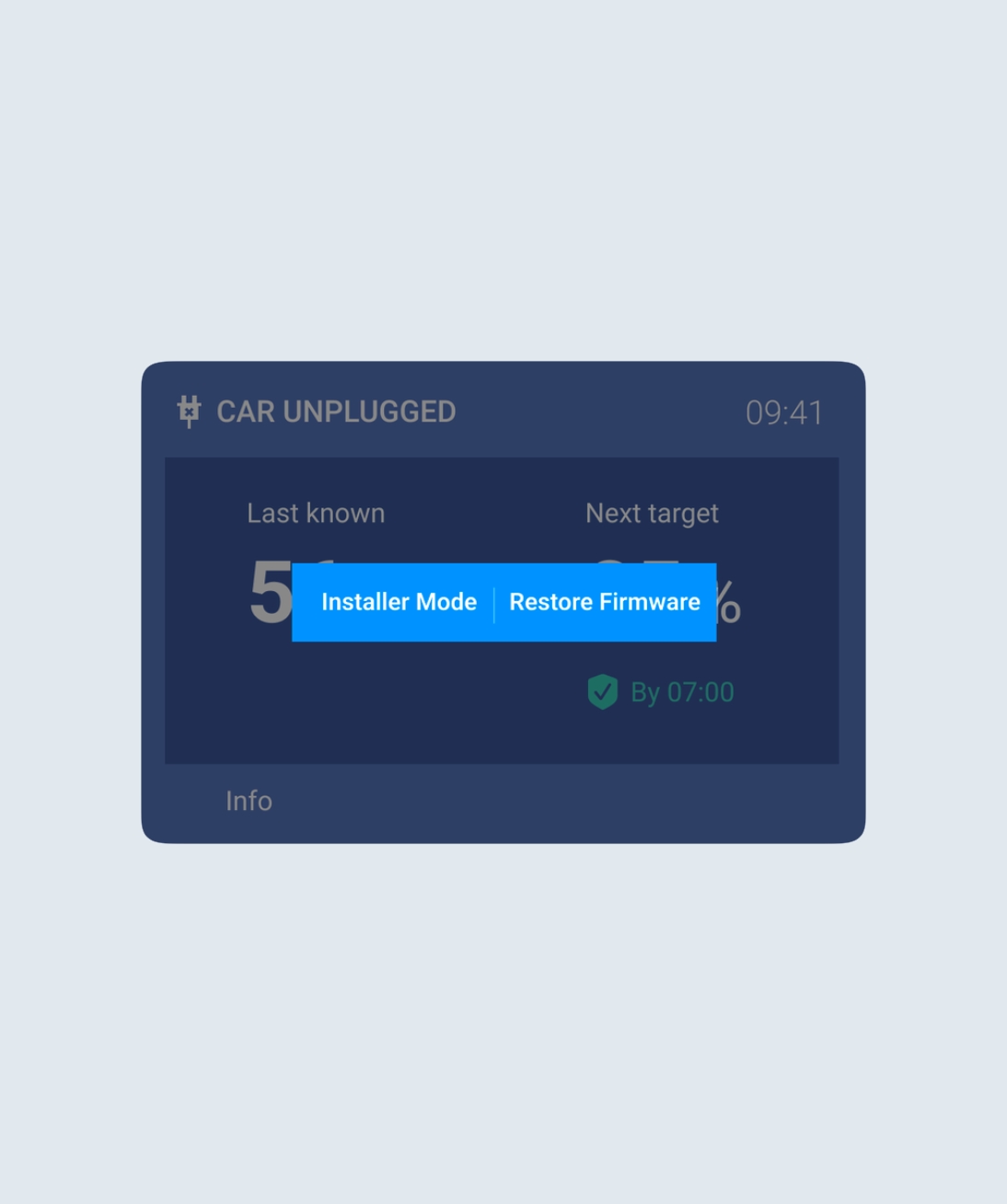
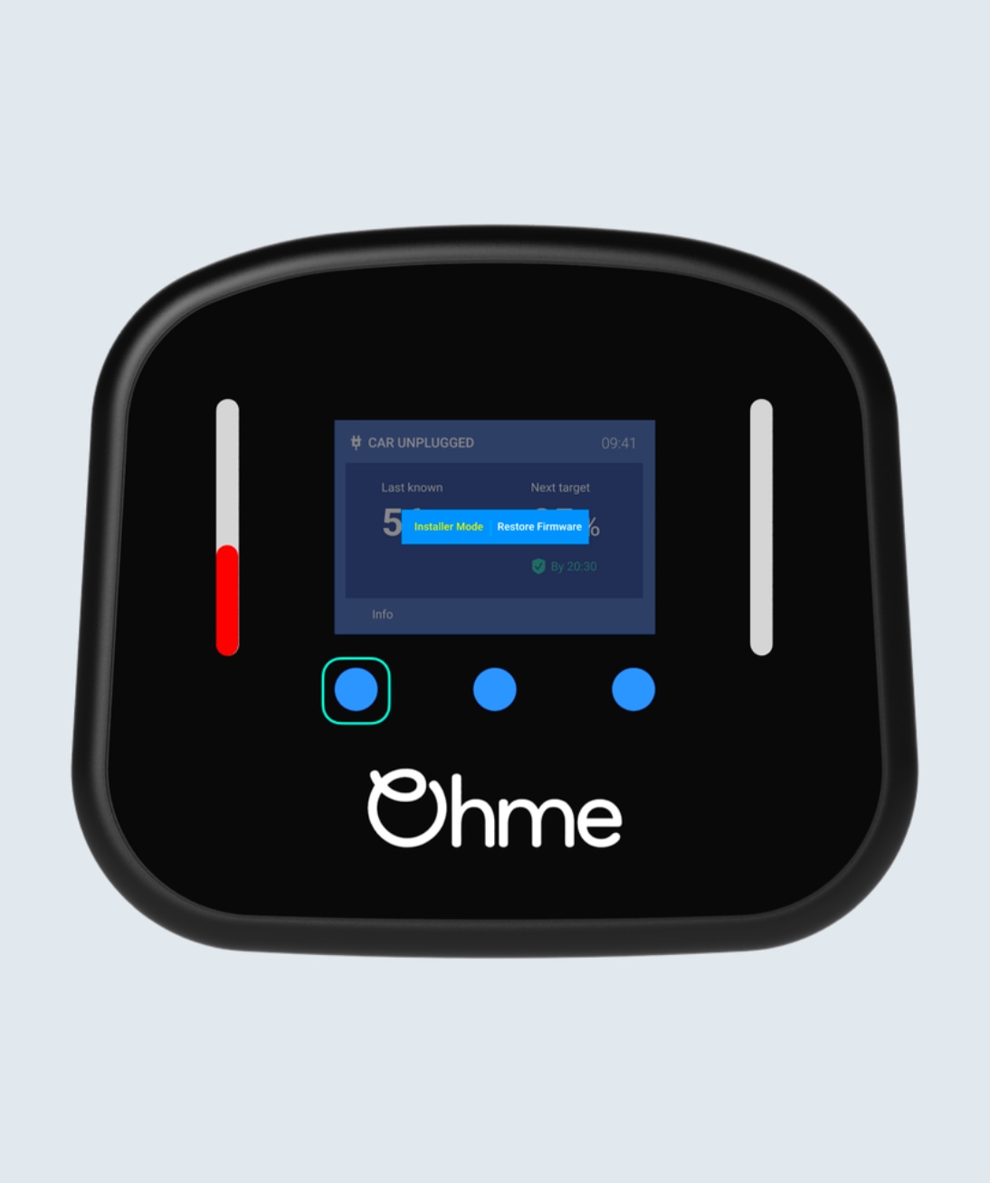
Once you have finished installing the CT clamp, you can use the Installer Portal or Installer Mode to check the clamp is reading data correctly.
Ohme ePod
Step 1
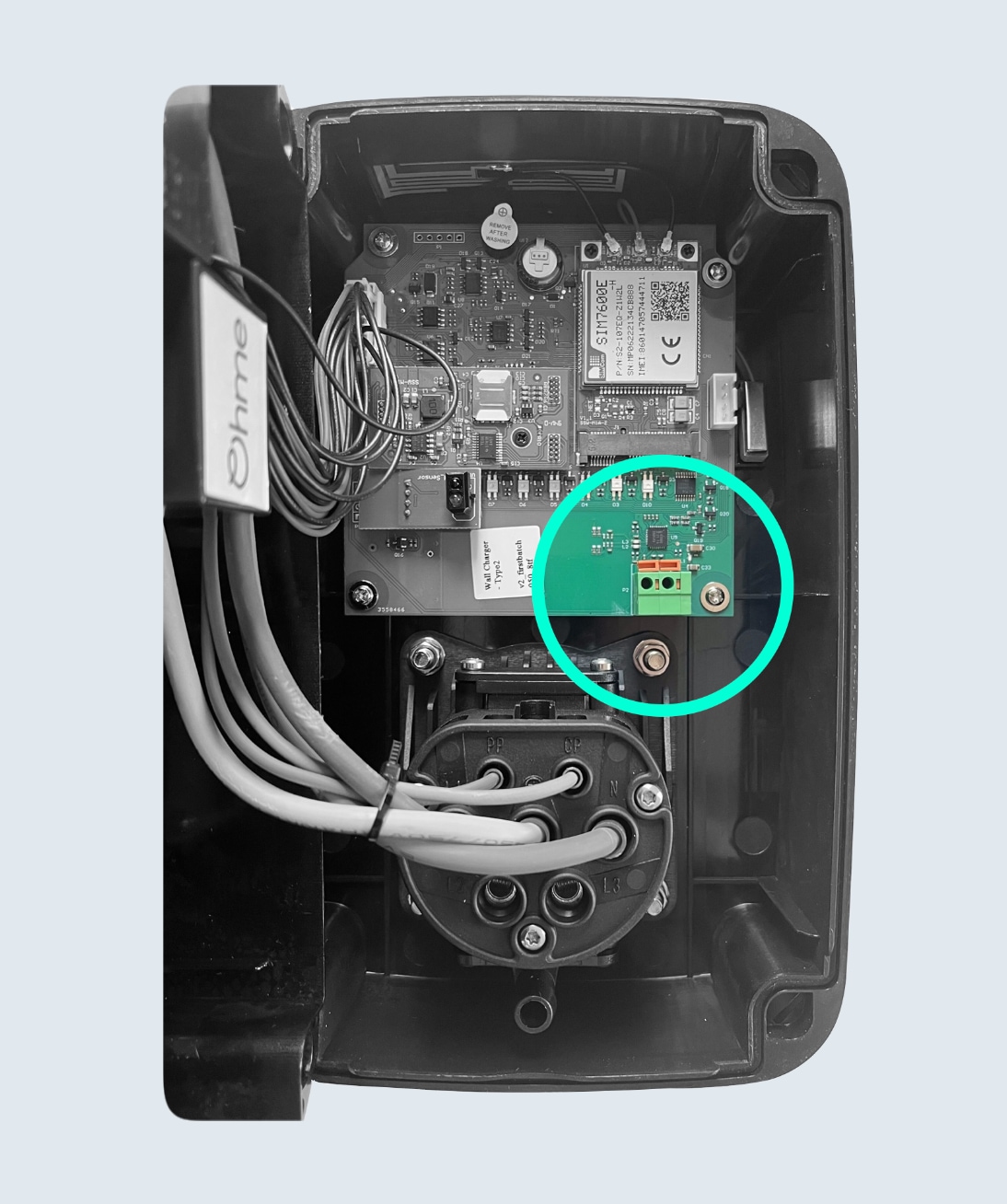
Open up the Ohme ePod and attach one end of the data cable to the front piece of the unit using the spring loaded connections.
Step 2
Once the first end is secured inside the unit, join the other end of the data cable to the CT clamp wired inside the Wago box.
Step 3
Now the data cable and CT clamp wires are joined, attach the CT clamp closest to the cable exiting the smart meter.
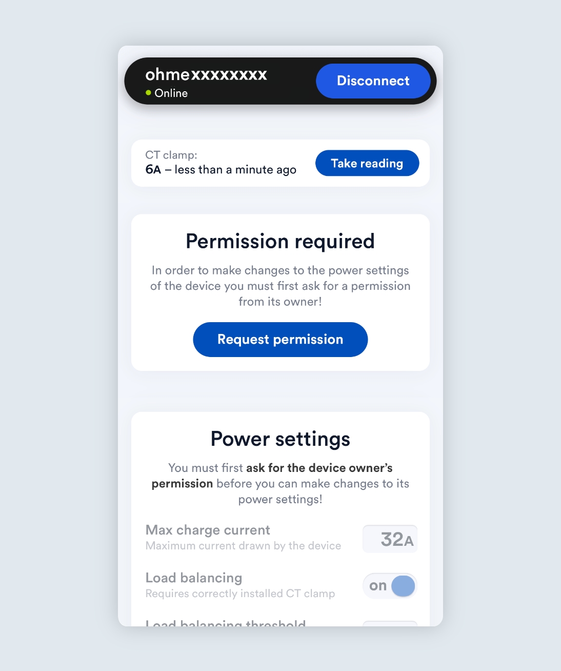
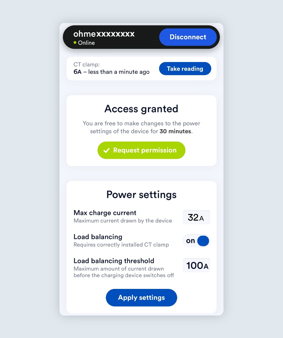
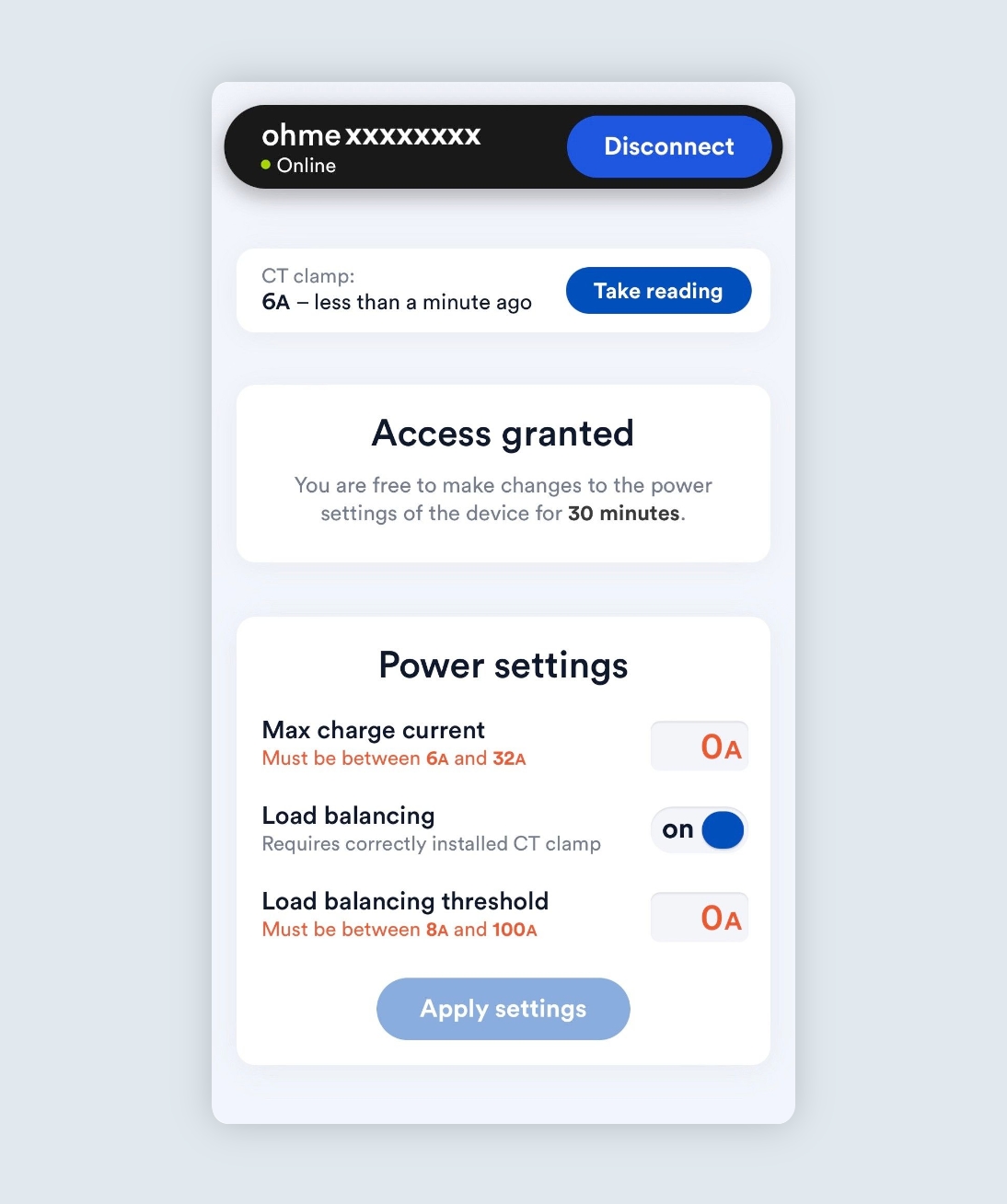
Take CT clamp reading
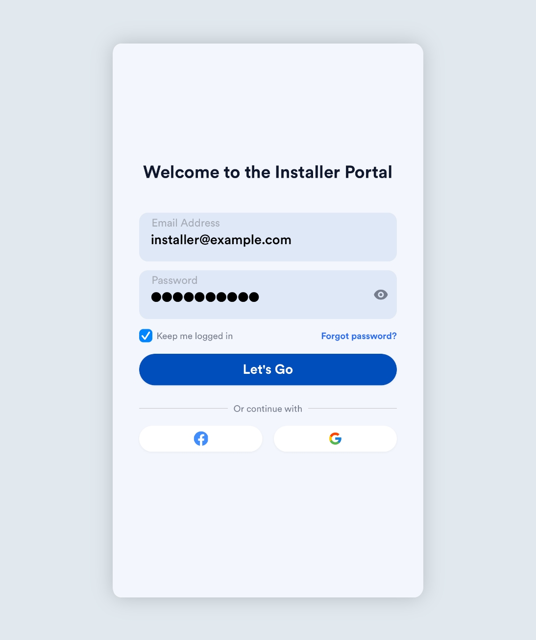
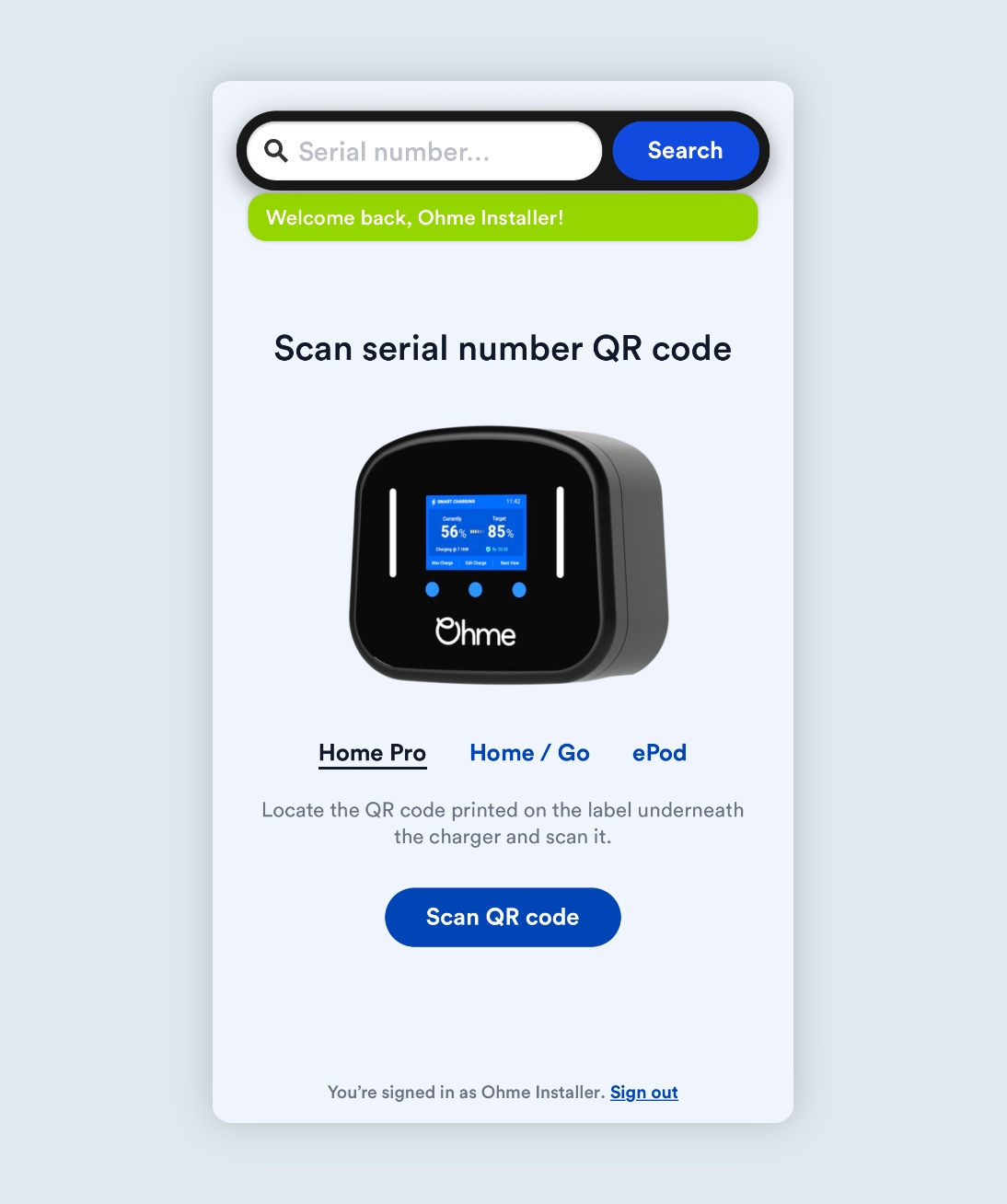
Installer Portal
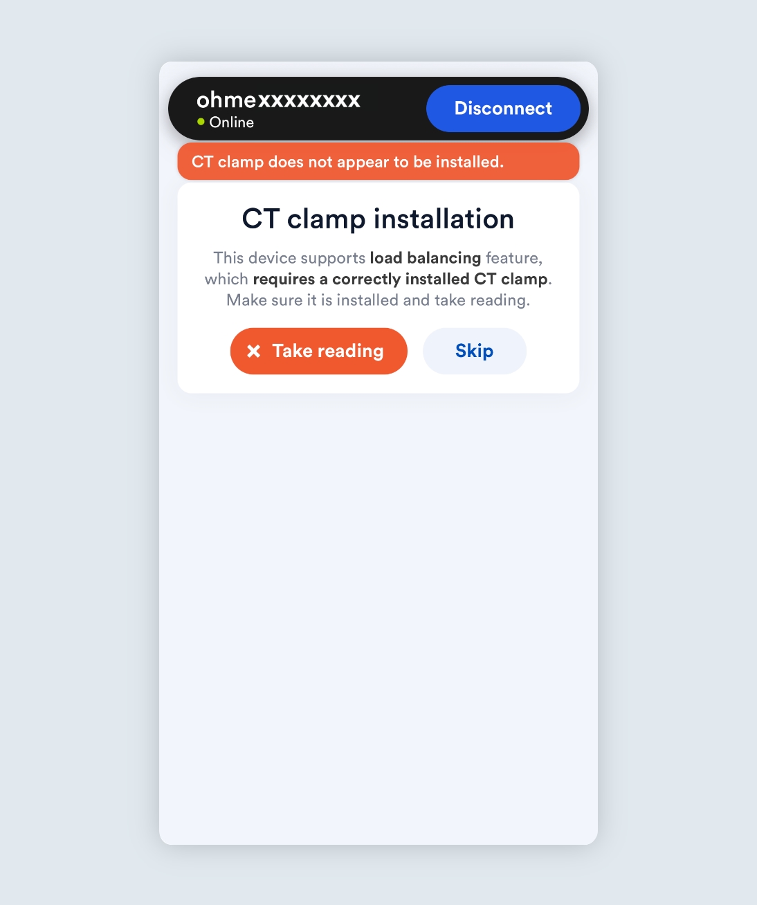
Once you have finished installing the CT clamp, you can use the Installer Portal or Installer Mode to check the clamp is reading data correctly.
Tip: Sometimes the electricity usage can be too low to trigger a reading. Turning on an appliance such as a kettle or toaster can help to increase the electricity usage and confirm the CT clamp is connected successfully.
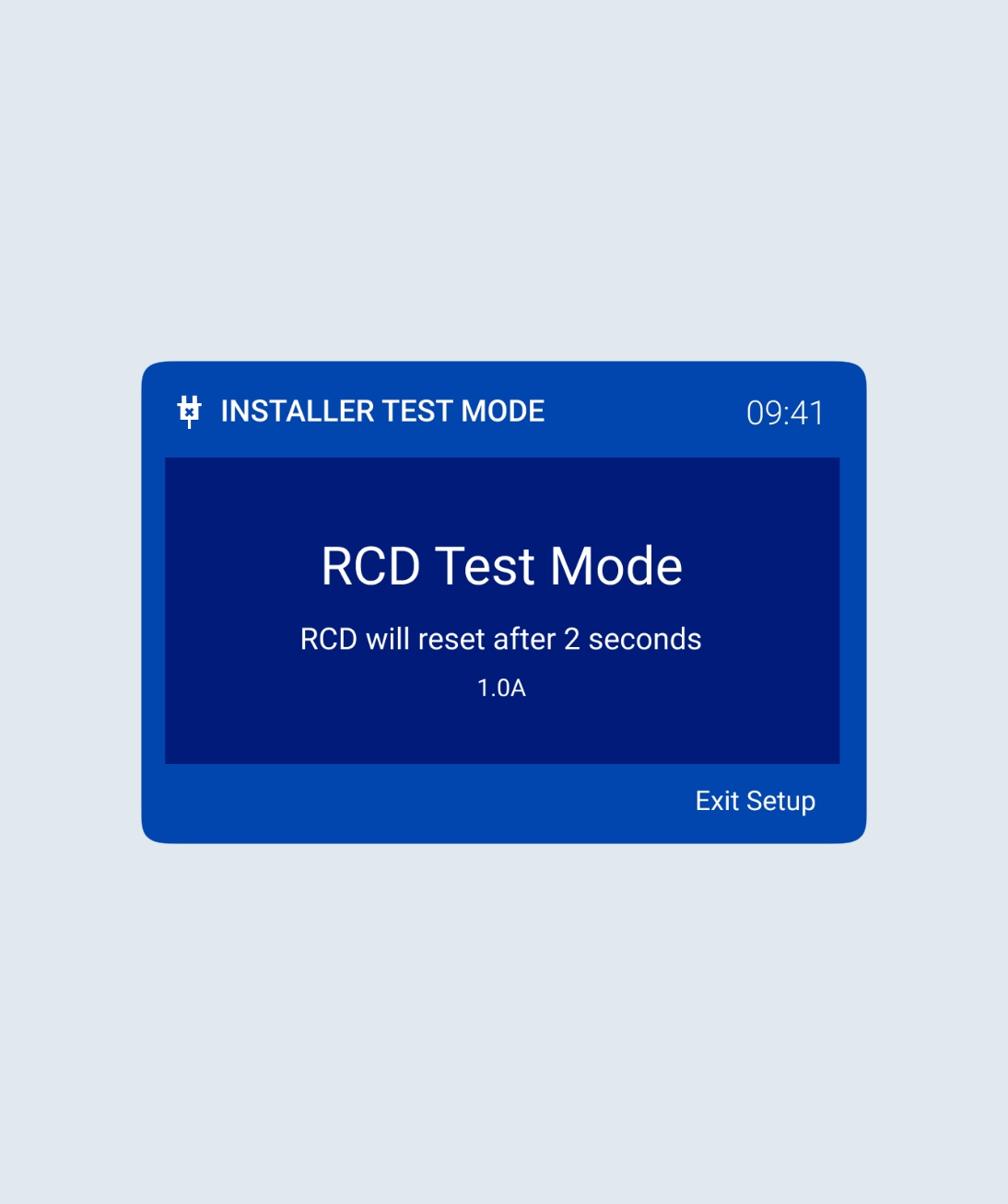
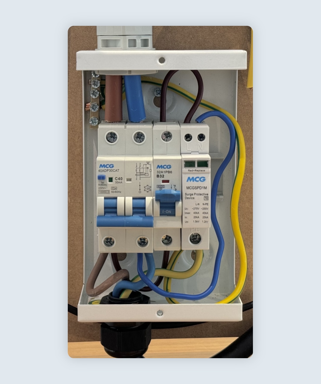
The RCBO (Residual current Circuit Breaker with Overcurrent protection) is a crucial safety device in any electrical circuit, protecting against earth faults, overloads, and short circuits. If the RCBO has tripped, this guide will walk you through the steps to safely reset it and restore power to the charger.
Checking the RCBO
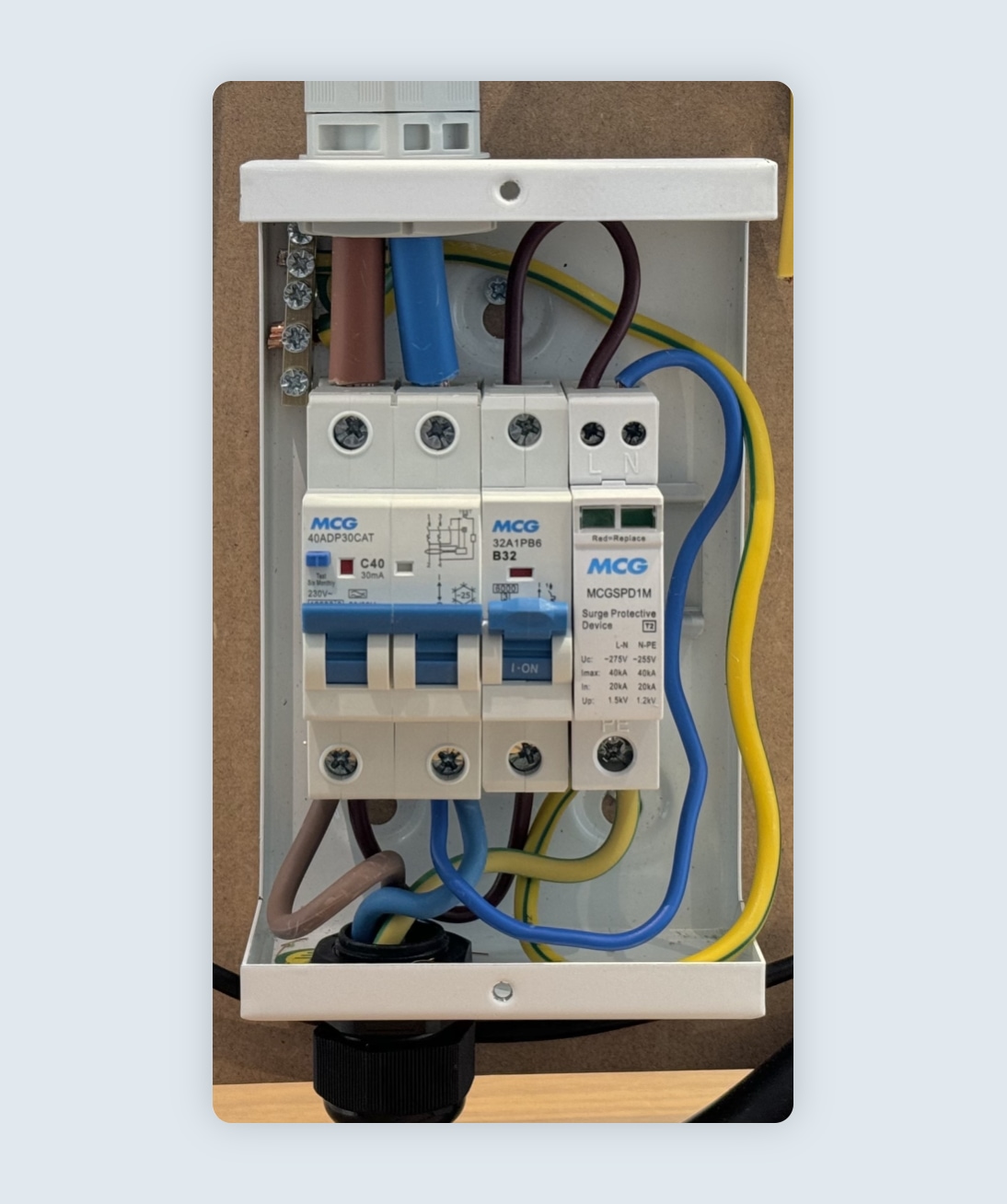
Power is OFF
When the trip switch is fully down the power is OFF.
Power is ON
When the trip switch is fully up the power is ON.
Tripped
When the trip switch is floppy and won’t stay in the up position the RCBO has tripped and will require a reset.
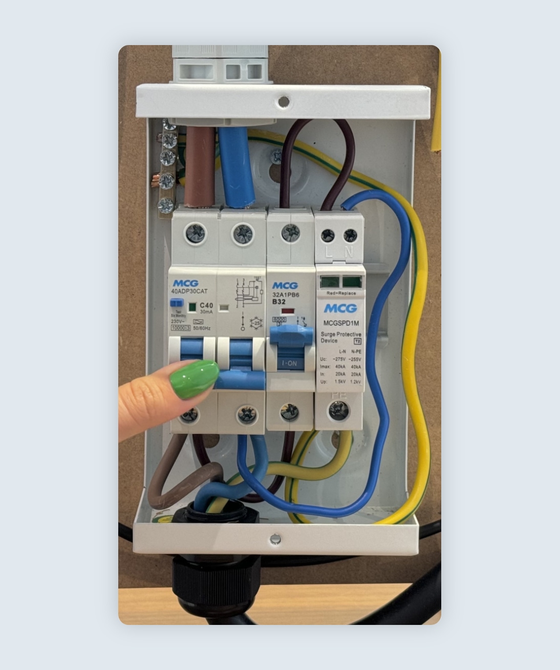
Resetting the RCBO
Step 1
To reset the RCBO, press the switch down using both parts of the switch.
Step 2
Firmly press the switch down until you hear a ‘click’. This confirms the switch has been reset.
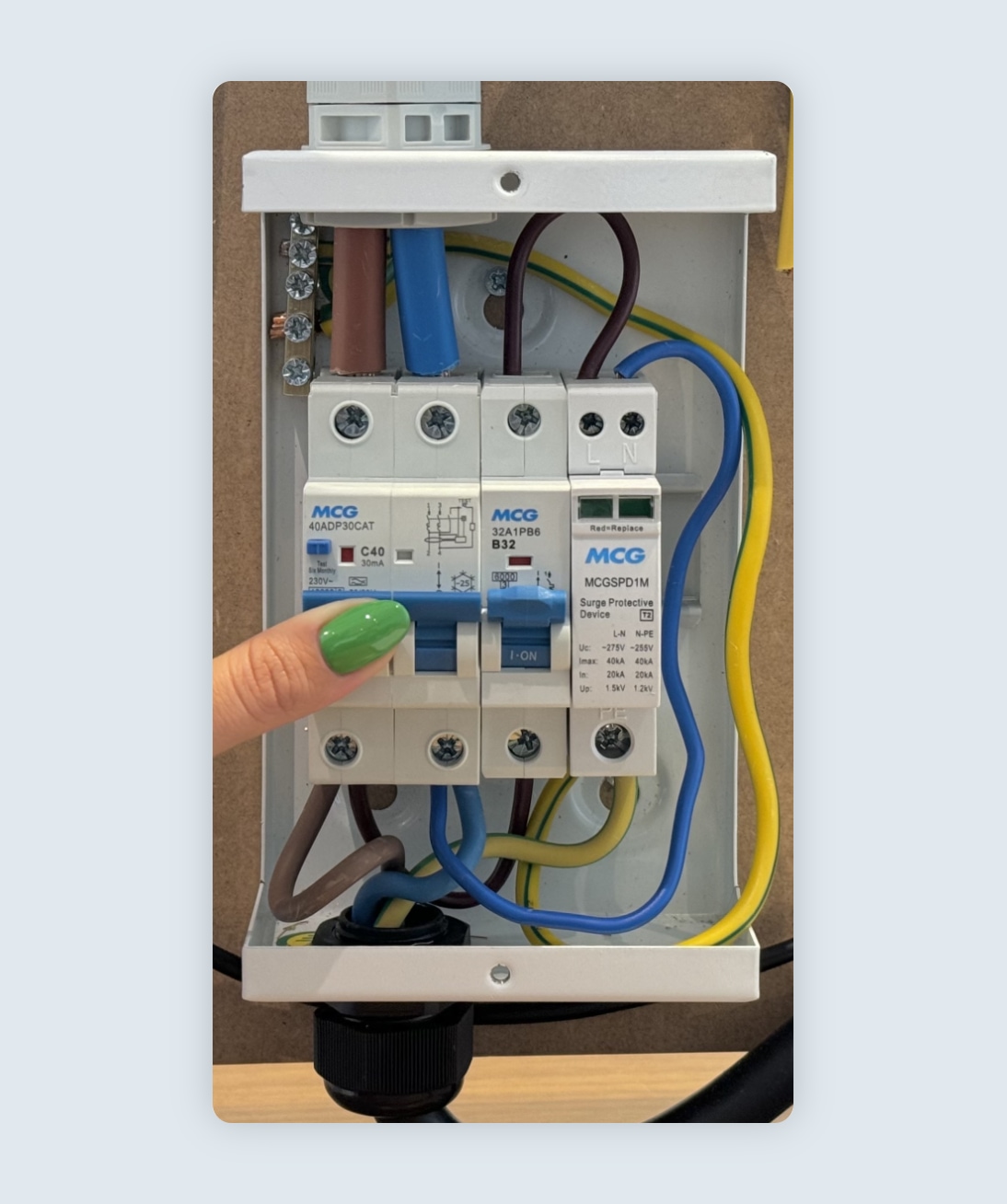
Step 3
Push both parts of the switch up into the ‘ON’ position. The switch should stay in place and power will be restored to the charger.
Note: If the RCBO does not stay in the ‘ON’ position, this could indicate a wiring issue or a fault with the RCBO itself. In such cases, a qualified electrician should be contacted.
The installation must be compliant with the IET Wiring Regulations and the IET Code of Practice for Electric Vehicle Charging Equipment. Installation should be carried out by a competent electrician with appropriate knowledge of EV charge point installations.
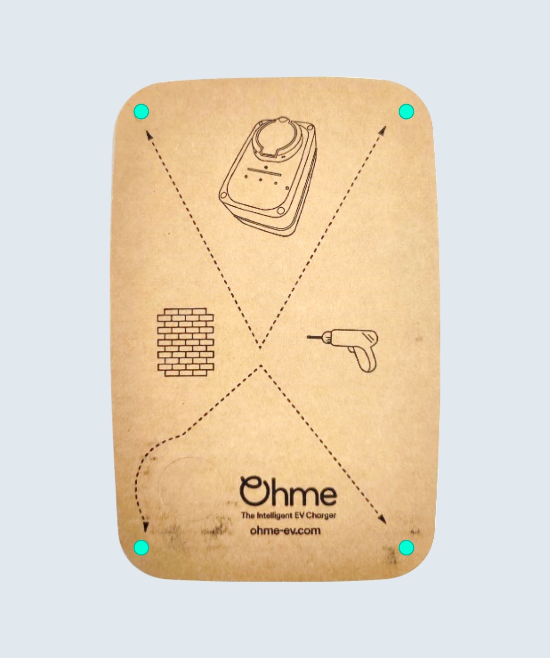
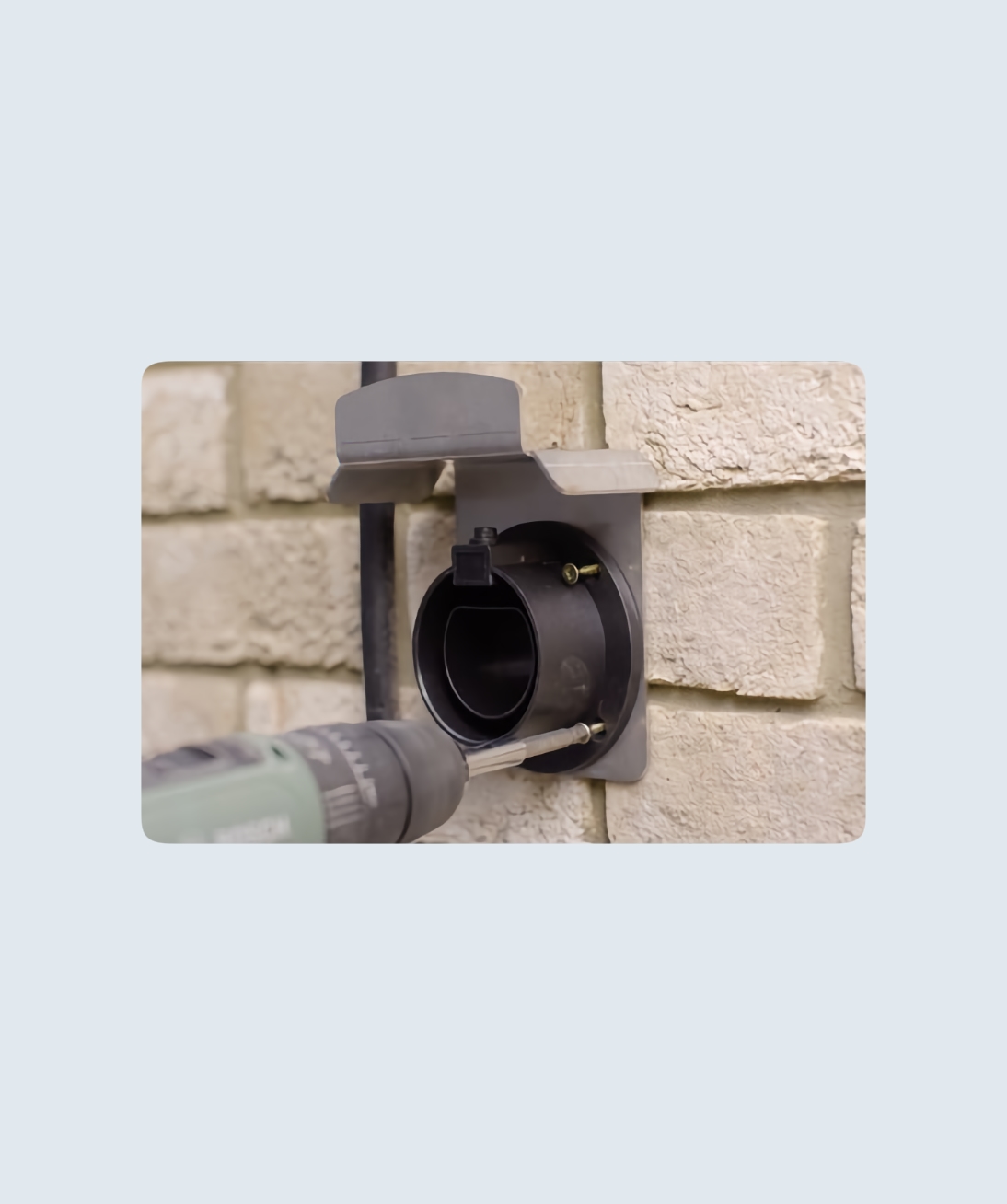
Step 1
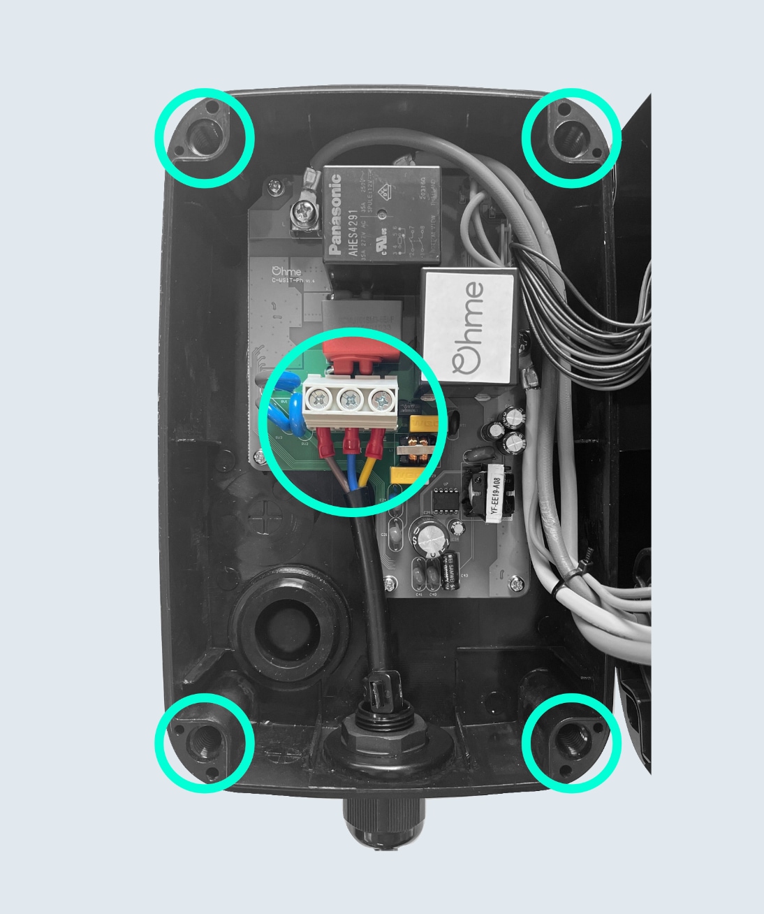
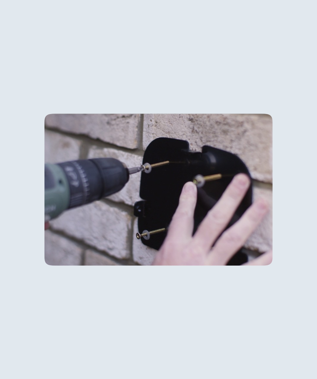
Using the drill template provided in the box, drill holes using a 7mm drill bit. Remove the front cover of the Ohme ePod and mount the back piece onto the wall using the screws provided.
Step 2
You can feed the input cable either through the gland in the back or underside of the Ohme ePod. Once you’ve done so, connect the Live, Neutral, and Earth wires.
Step 3
The Ohme ePod has a dynamic load balancing feature. A current sensor (CT) clamp is provided to measure the electrical demand of the property, or sub-board. The unit will limit the maximum current available to the vehicle to keep the household demand below the set threshold or fuse value. Secure the wires of the data cables in the spring loaded Wago located on the front of the unit.
If you’re using a separate data cable and have already used the underside hole for the main cable, use the back hole to feed the cable into the unit.
Note: you’ll require a second gland (M12 or M16) to maintain a weatherproof seal.
Step 4
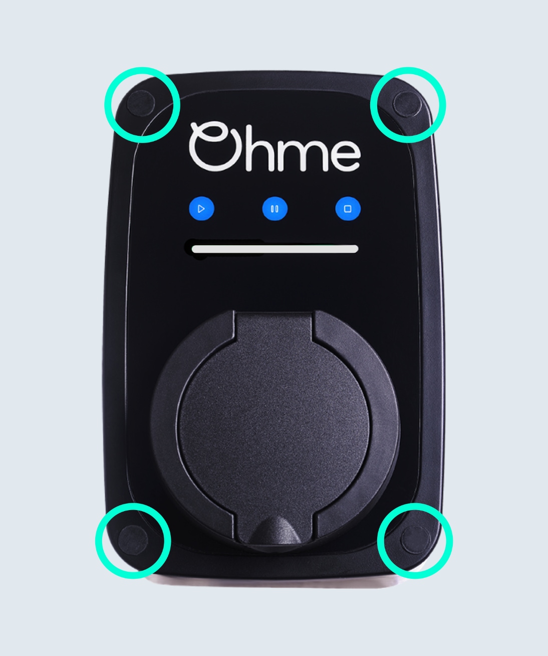
Reattach the front cover and install the screw caps provided with the Ohme ePod.
Installation complete
Now that you’ve successfully installed the Ohme ePod, check out the following article for how to commission an Ohme charger.
The installation must be compliant with the IET Wiring Regulations and the IET Code of Practice for Electric Vehicle Charging Equipment. Installation should be carried out by a competent electrician with appropriate knowledge of EV charge point installations.
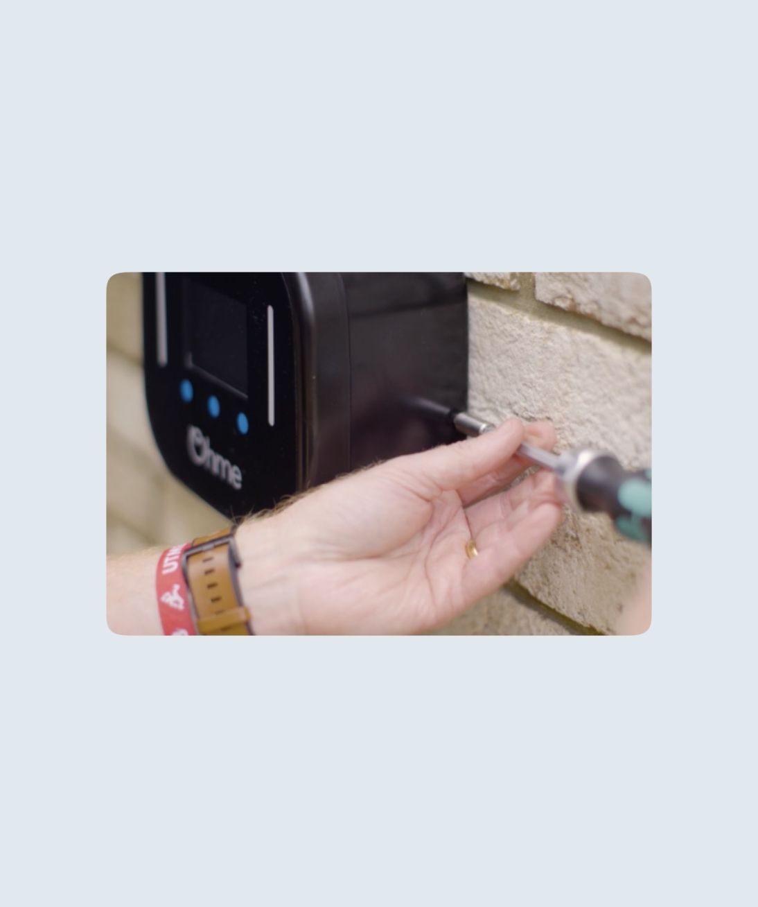
Step 1
The Ohme Home Pro is designed to be wall mounted to a flat surface. Fixings are included which are suitable for most wall surfaces (e.g. brick/render) but the installer should select their own fixings if these are not appropriate.
Attach the back plate to the wall using the four fixings supplied.
Step 2
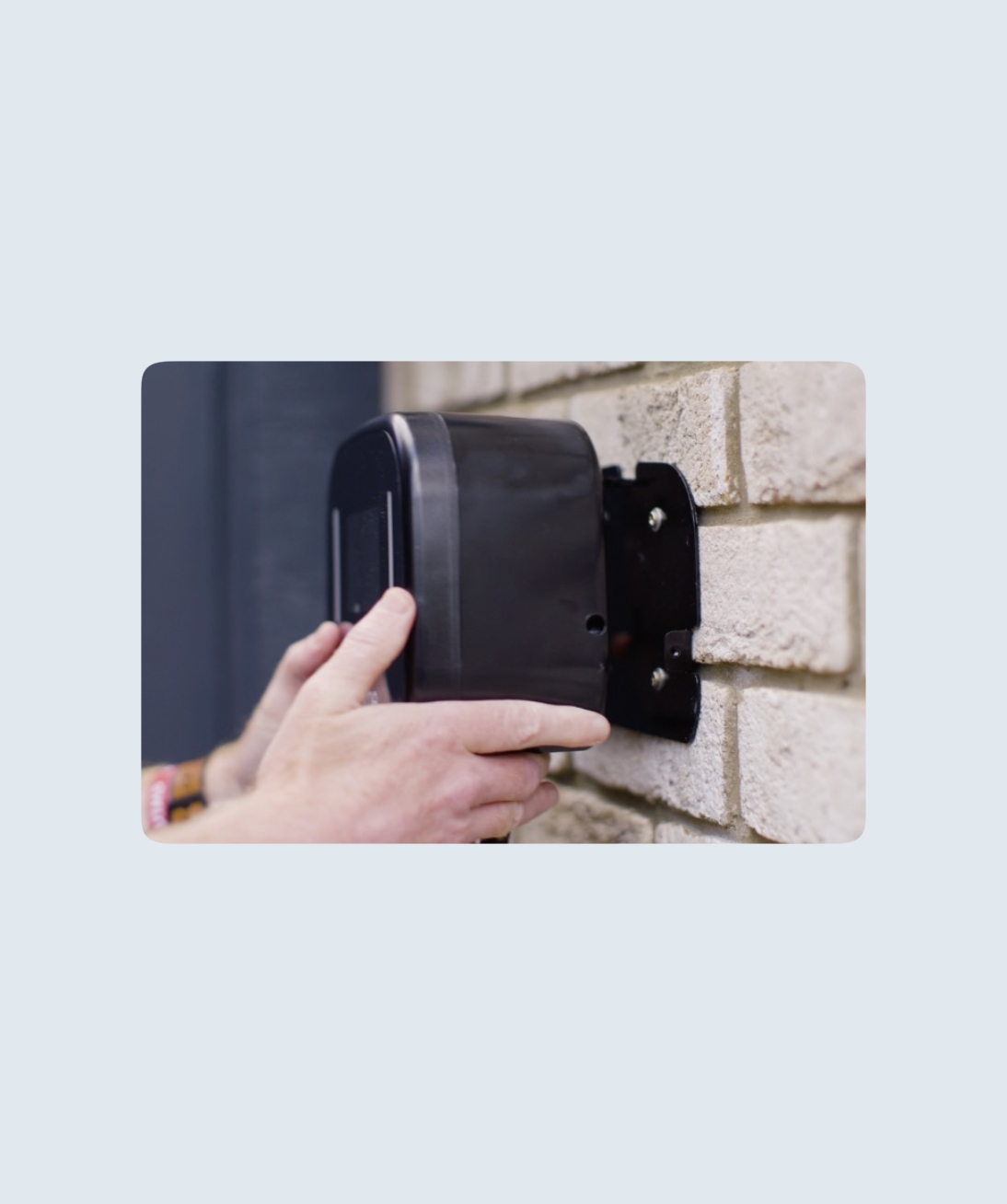
Mount the unit, carefully guiding the three lugs into the rear of the unit.
Step 3
Use the supplied three M4 short machine screws to fix the unit to the back plate.
Step 4
The Ohme Home Pro is supplied with a one metre fixed input cable/flying lead requiring termination on-site to a suitable junction box, isolation switch, or mini-CU (not supplied). The flying lead conductors are 6mm2 copper, the overall diameter is 15.2mm, suitable for a No. 6 cable cleat.
To connect, typically an installer will either:
· Install a junction box at ankle height
· Feed the input cable through a wall and terminate on the other side
Note: The junction box needs to be rated to at least 32A, have sufficient IP rating for the location, and have space for a three-way terminal block (no load balancing) or five-way terminal block (with load balancing).
Step 5
The Ohme Home Pro has a dynamic load-balancing feature. A current sensor (CT) clamp is provided to measure the electrical demand of the property, or sub-board. The unit will limit the maximum current available to the vehicle to keep the household demand below the set threshold/fuse value.
Where load balancing is activated, if the CT clamp is removed, installed in the wrong location or is faulty, the unit will revert to charge at a maximum of 16A. It is therefore sensible to ensure the spare capacity, after taking account of other loads and diversity, is at least 16A.
Step 6
The charger comes complete with a cable holder and charging gun holster to retain the cable and vehicle connector when not connected to the vehicle. Use a further four fixings to mount these to the wall.
Once the charger is installed and connected to power it will turn on and be ready for commissioning.
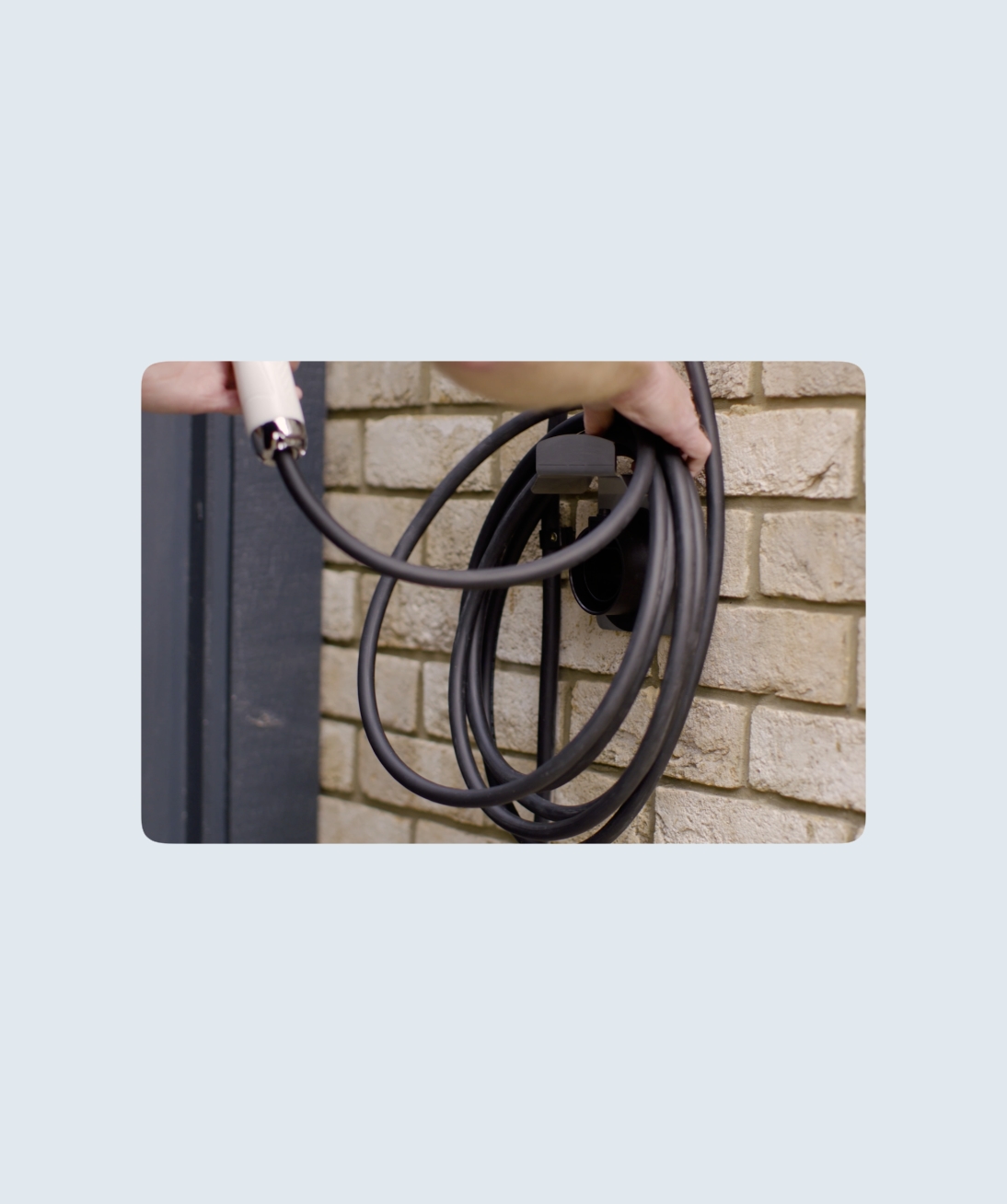
Storage while not in use
When the charger is unplugged from the vehicle it must be stowed away correctly.
Wrap the cable around the cable holder.
The charger plug must be pushed into the holster, you will hear a click when it is locked in place. This protects the charging pins from the elements. Push the button on the top of the holster to release the charging plug.
Installation complete
Now that you’ve successfully installed the Ohme Home Pro, check out the following article for how to commission an Ohme charger.